Terrain tracking
Design on the ground as it is.
Draw the field in 2D as you do today, then convert it onto bare-earth elevation. Your racking rules decide which frames stay.
Per frame
Near-shading, not an infinite-sheds approximation
Both
Fixed-tilt tables and single-axis trackers
Either license
Terrain attaches to a seat
An add-on, not a tier
What changes when the layout sits on the real ground?
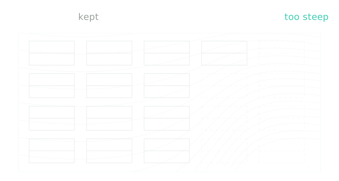
Which frames survive
Frames outside your racking product’s along- and across-slope limits come off on conversion, so the capacity you quote is the capacity that fits.
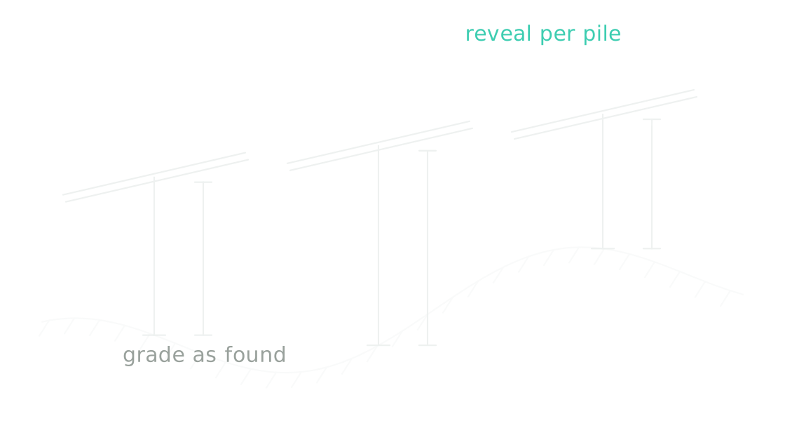
Pile reveals
Reveal and module clearance are solved per pile as part of the layout, so the pile schedule moves when the layout does. Embedment stays with your racking vendor.
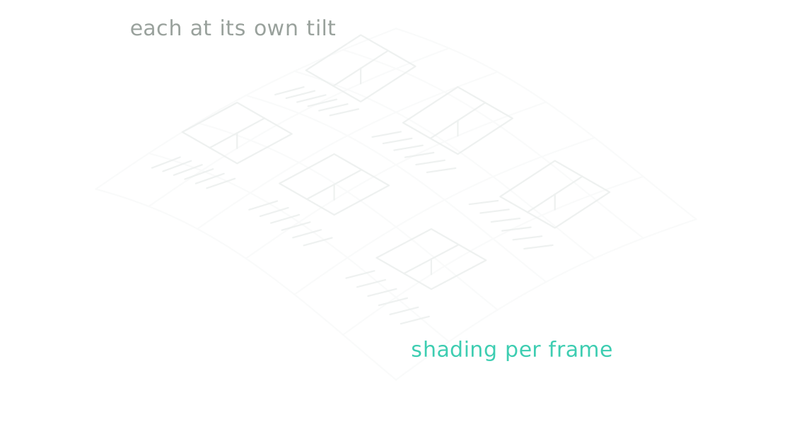
Shading per frame
Near-shading is computed frame by frame, each at its own tilt on the contour, with horizon shading on, in the engine that built the layout.
Where terrain tracking stops.
The limits an engineer checks first, stated plainly.
- Cut and fill, grading plans
- Not modeled. Earthworks stay with your civil engineer.
- Embedment depths
- Not calculated. We solve reveals; embedment is your racking vendor’s.
- Structural and geotechnical analysis
- Not performed.
- Survey, drone or CAD data
- Cannot be imported.
- Bare-earth elevation
- Neither survey grade nor construction accurate.
The detail, if you want it.
Six questions, answered plainly, with the limit included in each. Open what applies to you.
What is terrain tracking in Solesca?
It is the capability that places your racking on bare-earth elevation rather than on a flat plane, and then simulates what that costs you in energy. Frames sit on the ground as it falls, held inside the along- and across-slope tolerances your racking vendor allows; frames that exceed those tolerances come off the layout automatically. The layout reports the pile reveals, clearances and motor placement that result.
Think of it as a buildability instrument rather than a 3D view. Reveals, pile counts, slope limits and motor counts change the cost of a project on gentle ground too — the 3D is how you see it, not what it does for you.
How does Solesca model sloped solar sites?
You draw the field in 2D exactly as you do today, then convert that same field onto the terrain. The elevation grid comes with it, and your racking product — a reusable set of slope tolerances, reveals, clearances and pile configuration, attached to a design template — decides what survives the conversion.
The two limits do different jobs, and engineers test this. The across-slope limit governs the twist from one side of a frame to the other and modifies the frame’s own tilt. The along-slope limit governs the fall running down the length of a table or a tracker row and constrains the underlying topography rather than the tilt. Across slope is usually the tighter of the two, and it is the one that quietly deletes rows on a site with a perfectly acceptable average grade.
Does the energy model account for terrain?
Yes, and this is the part that differs in kind. Most tools — PVcase, PVsyst, HelioScope, SAM — approximate row-to-row shading with an infinite-sheds model, which assumes every row is identical and endlessly long on flat ground. On a slope that assumption breaks first and quietly.
Solesca computes near-shading frame by frame, using each frame’s own tilt and azimuth, the actual contour and horizon data, in the same engine that produced the layout. So the yield number and the layout are the same model rather than two drawings to reconcile — which is usually the answer to “why is my production three percent off?” The terrain was shading the array, and the flat model never knew.
What elevation data does Solesca use?
Bare-earth elevation — the ground surface with vegetation and structures removed — covering the site you draw, pulled in when you convert the field. It is what the layout and the shading both run against.
What it is not is a survey, and we will not pretend otherwise. It is not survey grade and it is not construction accurate. The job it does is to get you as close to a survey as you can get without paying for one, which is what you need at the stage where you are deciding whether a site is worth surveying at all. Your independent engineer still validates, and the survey still happens.
Can Solesca do cut and fill or grading plans?
No. Solesca fits racking to the ground as found. It does not move earth, model cut and fill, produce a grading design or estimate earthwork volumes, and a project whose engineering turns on those numbers needs a civil tool for that part.
What it answers is the question before that one: how much of this site works without moving earth, and where. On most C&I and community solar ground-mount projects, that is the question that decides whether the project is worth pricing at all — and it gets asked weeks before anyone will pay for a grading study.
What slope tolerances can I set for my tracker?
Four dials do most of the work, and they are interdependent: maximum along-slope, maximum across-slope, pile reveal and minimum module clearance. Push the reveal up and more frames survive on steeper ground, at the cost of longer piles; walk it back to what you would order and frames drop out. That trade is the point of the tool, not a defect in it.
Reveal is where we stop: we do not give embedment depth. How far the pile goes into the ground is a function of soil and load, and it belongs to your racking vendor and your geotechnical engineer.
The rest are set on the racking product rather than per design, so engineering configures them once and everyone else inherits them. Fixed tilt is organized as tables and table groups, trackers as sections and section groups, and drive line and rows per drive set the motor count that lands in the bill of materials.
| Parameter | Fixed tilt | Single-axis tracker |
|---|---|---|
| Maximum along-slope | Yes | Yes |
| Maximum across-slope | Yes | Yes |
| Pile reveal | Yes | Yes |
| Minimum module clearance | Yes | Yes |
| Bay gap | Yes | Yes |
| Piles per table | Yes | — |
| Line spacing and pile line | Yes | Yes |
| Section angle | — | Yes |
| Motor gap and motor hinge | — | Yes |
| Wing angle | — | Yes |
| Drive line and rows per drive | — | Yes |
Bring us a site you are unsure about
The useful test is a site you priced flat and then lost to the grading, or one you passed on without modeling. Thirty minutes, your terrain, your racking spec, with our U.S.-based engineering team.